XLChain Jun, 2018
Overview
This is a course project of our Fabrication and Physical Prototyping course, implemented by Xincheng Li and Chengxi Xia. Blockchain is a hot topic recently, but only very few people know the theory behind it. This project want to introduce the simple mechanism of blockchain leveraging the tangible object interaction, under the constraint of the course requirement.
 XLCahin
We’ve already seen some interesting visualization about blockchain, like ethviewer, etc. Though it is inspiring to see these digital visualization, tangible visualization would be more fun to play with, thus easy to accept by broader range of people, especially young children.
Our initial thought was to use the resource we have at makerspace to show some basic consensus algorithm using in blockchain technology. Limited to the course constraint, we narrow down the scope to a scenario that only show the abstract level of blockchain information convey mechanism, which is how one block transfer information to another one.
The finished video is as below.
Implementation
The system block diagram is shown as below.
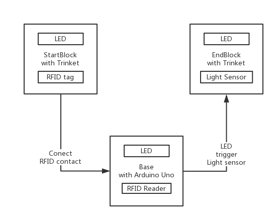 Block Diagram
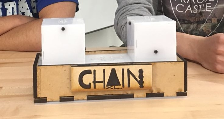
Two parts we have are two blocks and the base. As can be seen in the video, the chain on base is originally white LED state, and the start block is green LED state, while the end block is white LED state. When two blocks are put on to the base, RFID tag in the start block will be read by the RFID reader in the base. Then the chain on the base will start to shine green LED one by one, and finally after 5 rounds show green LED state on the whole chain. When the green LED at the end of chain lights on, the light sensor in the end block will sense that, which will trigger the end block to green LED state.
The detail implementation method will be shown in the Appendix separately.
Reflection
In the process of implementing it, we learn all sorts of new things. From the beginning we have no clue how to fasten the PCB board on the base and how to tie the two boards without glue, we learn step by step from trial and error lots of versions to the final one. And we have several experiences to share.
- Measure is the first and very important step. With an accurate measure and computing, a lot of time can be saved later. Sometimes when we use Rhino, we hope there is a system that can set some variable so that we can manage the dependence of all measurement very easily, instead of re compute and redraw all of the shape after changing one component.
- Physical world never works as smoothly as digital world. This is about fit test, one of the most time consuming part of the project. Only after laser cutting an acrylic board, can you find that laser has its dimension (about 1.5 mm diameter for our Universe laser cut machine) instead of the no dimension point in the digital world. So we tried lots of times to make two acrylic board fits without using an glue. And we even use two dimensions of cutting piece for block to make most of them fit very tight and only top of it fits a little loosely, so that it can be move out easier.
- Spray painting needs the mold fit the board very tight. Otherwise the paint will go to any space it can find and the figure will be blur.
Though lots of work have been put into this project. It’s still fun to make something by your hand and see it working. This project is very preliminarily in the way of tangible visualization of blockchain consensus algorithm. We believe with more projects like this, we can make the theory behind the scene more accessible to broader populations.
Appendix
Detail of blocks made by Xincheng
Hardware
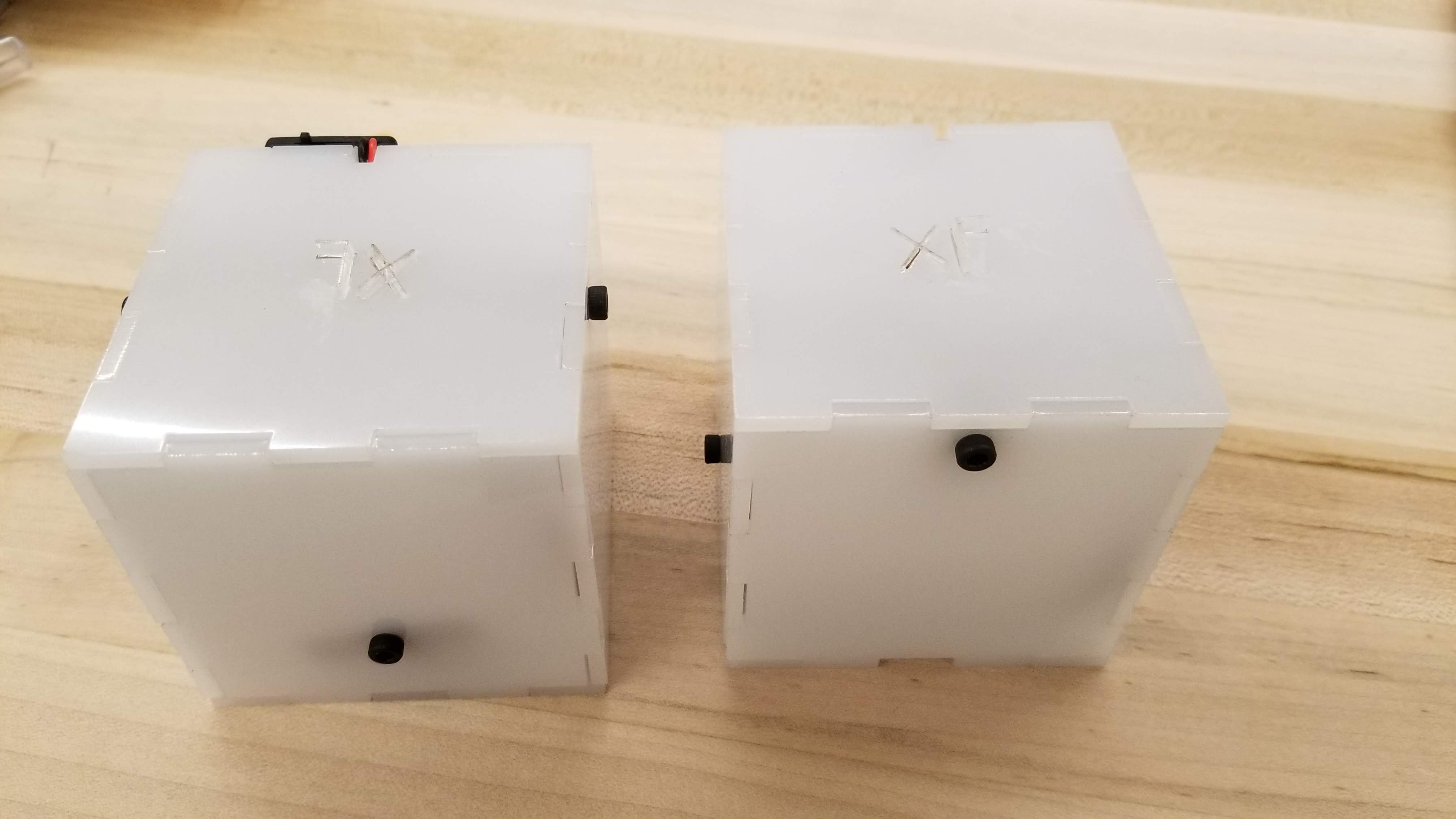 Block
Block
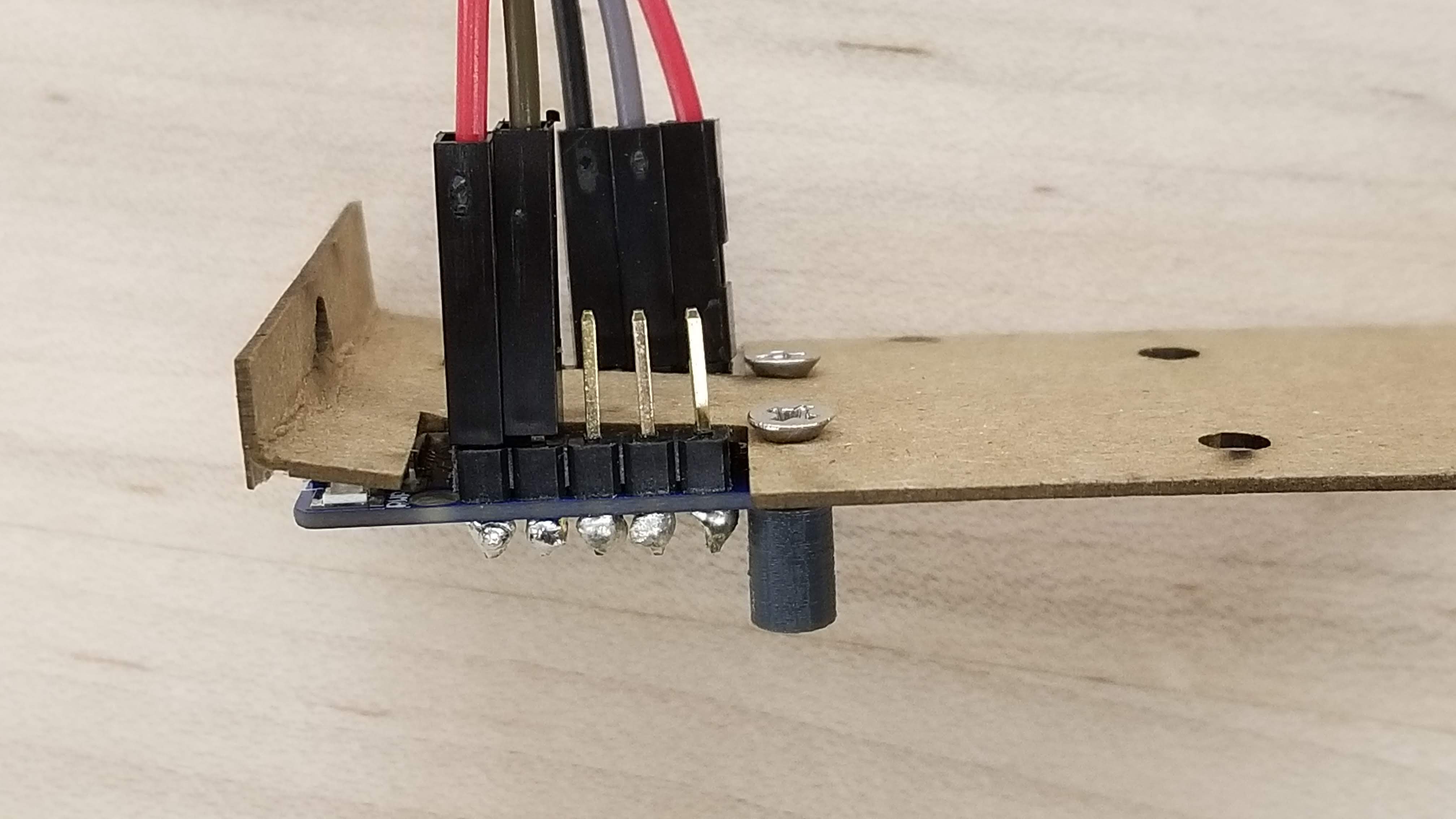
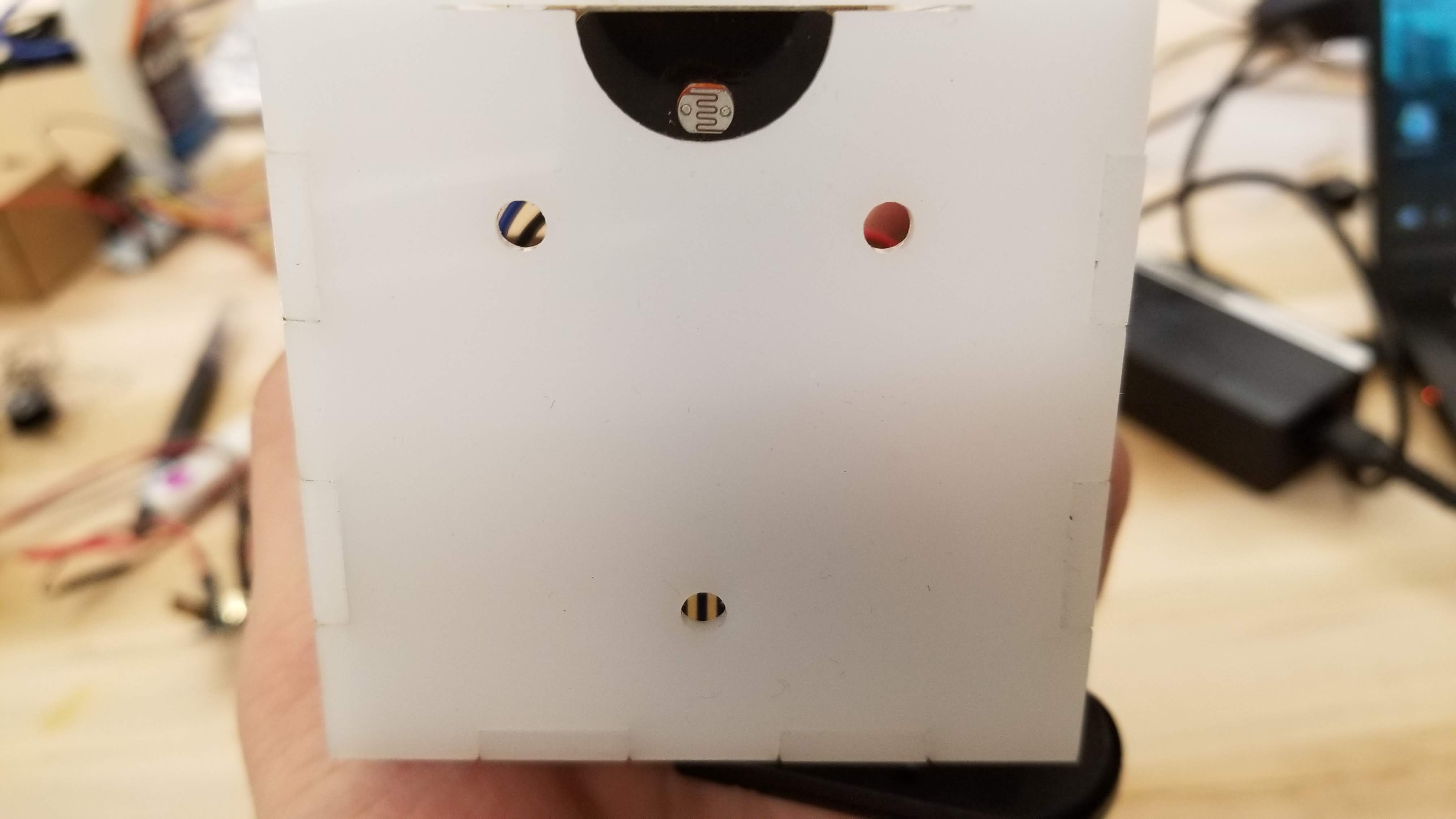 Block inside
 Light guide
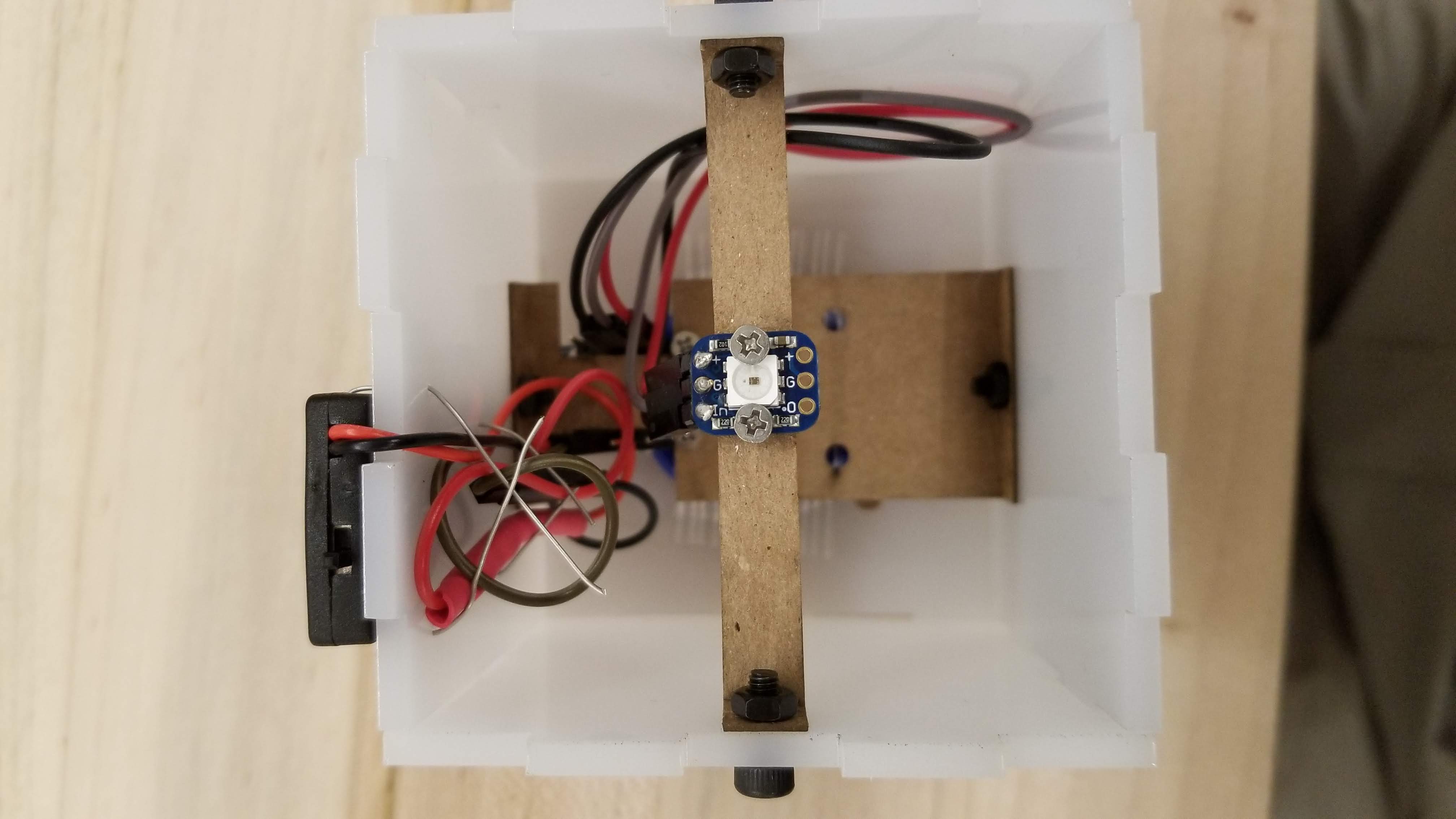 Block inside
 Fasten board
Software
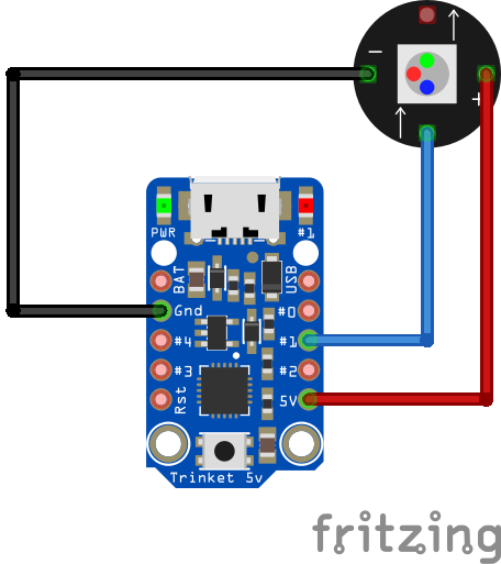 Startblock Schematics Layouts
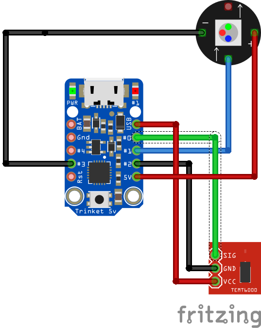 Endblock Schematics Layouts
Arduino code of start block. It just lights on the green LED all the time.
#include <Adafruit_NeoPixel.h>

const int LED = 1;
const int GND = 2;

const int NUMPIXELS = 1;
Adafruit_NeoPixel pixels = Adafruit_NeoPixel(NUMPIXELS, LED, NEO_GRB + NEO_KHZ800);

// the setup routine runs once when you press reset:
void setup() {
  // init digital ground
  pinMode(GND, OUTPUT);
  digitalWrite(GND, LOW);
  // initialize the digital pin as an output.
  pinMode(LED, OUTPUT);
  pixels.begin();
  showGreenLED();
}

// the loop routine runs over and over again forever:
void loop() {
}

void showGreenLED() {
    pixels.setPixelColor(0, pixels.Color(0,150,0)); // Moderately bright green color.
    pixels.show(); // This sends the updated pixel color to the hardware.
}
Arduino code of end block. It is the white LED state initially. When the light sensor sense the LED on the chain lights on, it will become the same green LED as the start block.
#include <Adafruit_NeoPixel.h>

const int LASERSENSOR = 0;
const int LED = 1;
const int GND0 = 2;
const int GND1 = 3;
const int USB = 4;
int SensorReading = HIGH;

const int NUMPIXELS = 1;
Adafruit_NeoPixel pixels = Adafruit_NeoPixel(NUMPIXELS, LED, NEO_GRB + NEO_KHZ800);

// the setup routine runs once when you press reset:
void setup() {
  // set up digital ground and 5v
  pinMode(GND0, OUTPUT);
  pinMode(GND1, OUTPUT);
  pinMode(USB, OUTPUT);
  digitalWrite(GND0, LOW);
  digitalWrite(GND1, LOW);
  digitalWrite(USB, HIGH);
  // initialize the digital pin as an output.
  pinMode(LED, OUTPUT);
  pinMode(LASERSENSOR, INPUT);
  pixels.begin();
}

// the loop routine runs over and over again forever:
void loop() {
  SensorReading = digitalRead(LASERSENSOR);
  if(SensorReading == LOW) {  // init status
    showWhiteLED();
  } else {  // when chain pass through
    showGreenLED();
  }
}

void showWhiteLED() {
    pixels.setPixelColor(0, pixels.Color(255,255,255));
    pixels.show();
}

void showGreenLED() {
    pixels.setPixelColor(0, pixels.Color(0,150,0)); // Moderately bright green color.
    pixels.show(); // This sends the updated pixel color to the hardware.
}
Detail of base made by Chengxi
Hardware
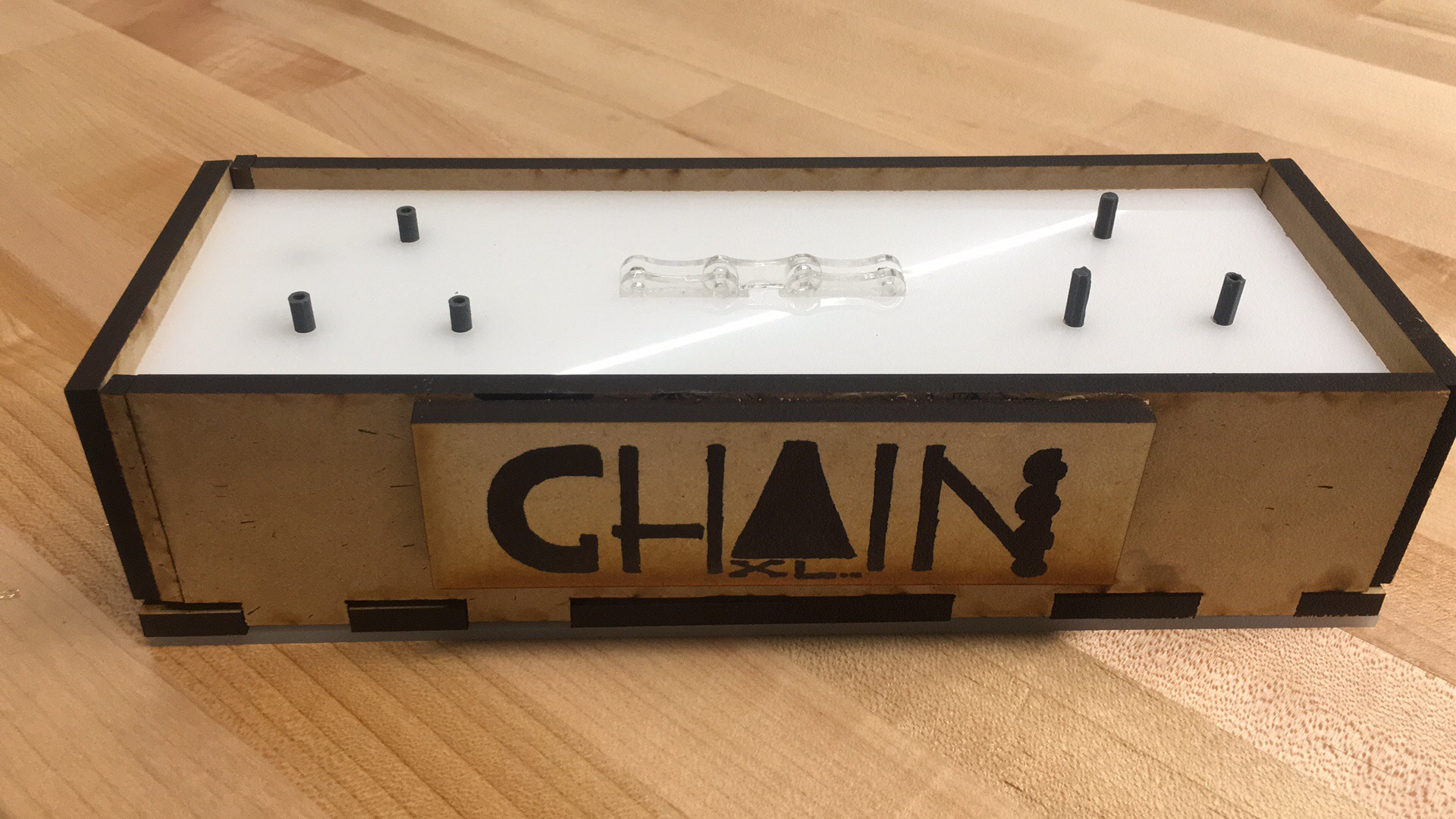 Base overview
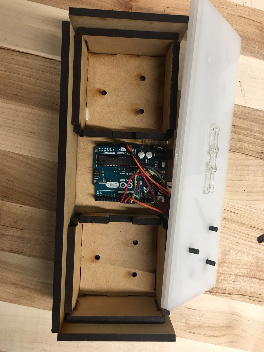 Base inside
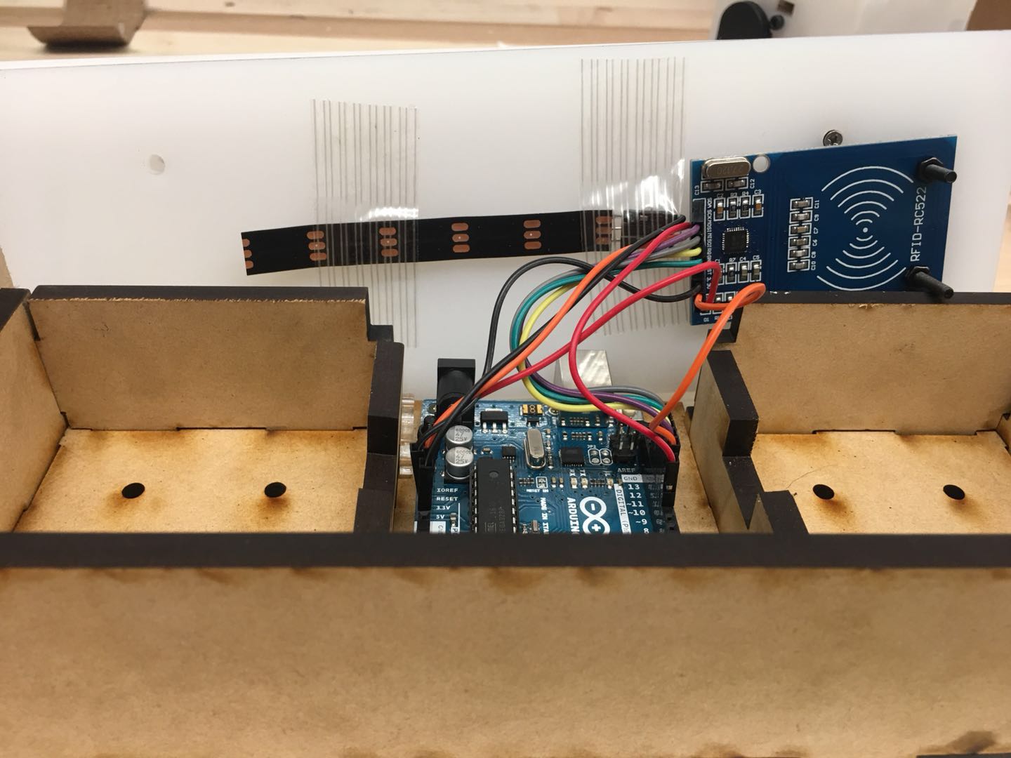 Electronic component
 Light guide
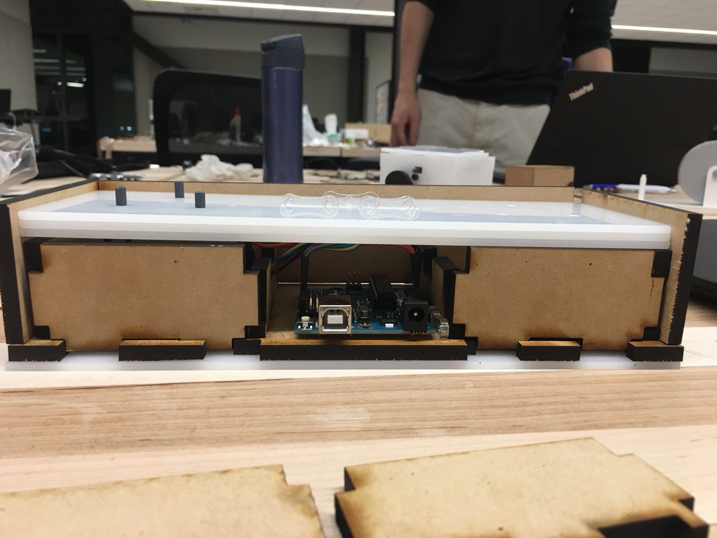
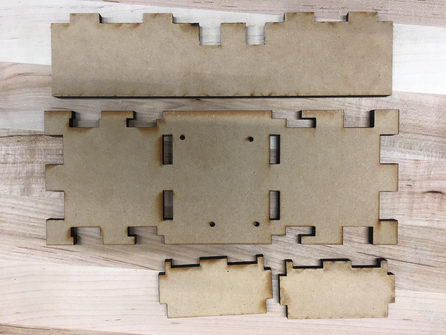 Enclosure
Software
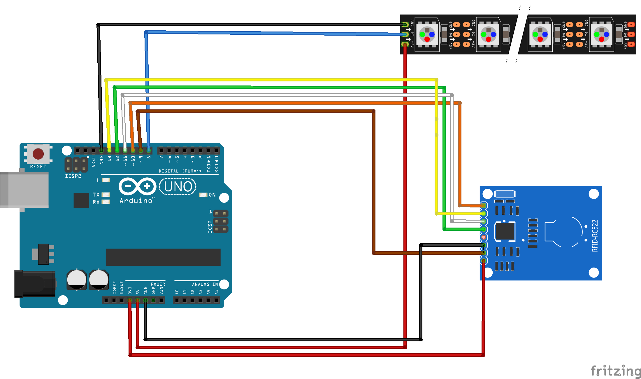 Base Schematics Layouts
Arduino code of base. Basically initially it lights on white led, if it read RFID tag, it will ring green led for 5 times one by one and then become all green LED.
/*
   --------------------------------------------------------------------------------------------------------------------
   Example sketch/program showing how to read new NUID from a PICC to serial.
   --------------------------------------------------------------------------------------------------------------------
    pin layout used:
    RFID Reader:
   -----------------------------------
               MFRC522      Arduino
               Reader/PCD   Uno/101
   Signal      Pin          Pin
   -----------------------------------
   RST/Reset   RST          9
   SPI SS      SDA(SS)      10
   SPI MOSI    MOSI         11 / ICSP-4
   SPI MISO    MISO         12 / ICSP-1
   SPI SCK     SCK          13 / ICSP-3

   Neopixel strip:
   ------------------------------------
   VCC         VCC          5V
   CND         GND          GND
   DIN         DI           8
*/

#include <SPI.h>
#include <MFRC522.h>
#include <Adafruit_NeoPixel.h>

#define PIXEL_PIN   8    // Digital IO pin connected to the NeoPixels.

#define PIXEL_COUNT 5   //number of pixel on the strip

constexpr uint8_t RST_PIN = 9;     // Configurable, see typical pin layout above
constexpr uint8_t SS_PIN = 10;     // Configurable, see typical pin layout above

MFRC522 rfid(SS_PIN, RST_PIN); // Instance of the class
int count = 0;// to delay the connection

// Parameter 1 = number of pixels in strip,  neopixel stick has 8
// Parameter 2 = pin number (most are valid)
// Parameter 3 = pixel type flags, add together as needed:
//   NEO_RGB     Pixels are wired for RGB bitstream
//   NEO_GRB     Pixels are wired for GRB bitstream, correct for neopixel stick
//   NEO_KHZ400  400 KHz bitstream (e.g. FLORA pixels)
//   NEO_KHZ800  800 KHz bitstream (e.g. High Density LED strip), correct for neopixel stick
Adafruit_NeoPixel strip = Adafruit_NeoPixel(PIXEL_COUNT, PIXEL_PIN, NEO_GRB + NEO_KHZ800);

void setup() {
  Serial.begin(9600);
  SPI.begin(); // Init SPI bus
  rfid.PCD_Init(); // Init MFRC522
  strip.begin();
  strip.show(); // Initialize all pixels to 'off'
}

void loop() {
  // Looking for RFID tag
  byte bufferATQA[2];
  byte bufferSize = sizeof(bufferATQA);
  MFRC522::StatusCode result = rfid.PICC_RequestA(bufferATQA, &bufferSize);

  //if tag found, showing running green pixels for 5 times, then steady green display
  if ( result == 0) {
    if (count < 5) {
      colorWipe(strip.Color(0, 255, 0), 5000); // green
      colorWipe(strip.Color(0, 0, 0), 5000);  //running mode
      count ++;
    }
    else {
      colorWipe(strip.Color(0, 255, 0), 5000);
    }

    rfid.PCD_StopCrypto1(); // Stop encryption on PCD

    //reopen the antenna to guarantee the reading success
    rfid.PCD_AntennaOff();
    rfid.PCD_AntennaOn();
  }
  //if no tag found, show only one white pixel and if the tag removed, show a running white mode one tiems and then back to one white pixel display.
  else {
    if (count >= 5) {
      colorWipe(strip.Color(127, 127, 127), 5000); // white
    }
    strip.setPixelColor(0, strip.Color(127, 127, 127)); // bright color.
    strip.setPixelColor(1, strip.Color(0, 0, 0)); // off
    strip.setPixelColor(2, strip.Color(0, 0, 0)); // off
    strip.setPixelColor(3, strip.Color(0, 0, 0)); // off
    strip.setPixelColor(4, strip.Color(0, 0, 0)); // off
    strip.show(); // This sends the updated pixel color to the hardware.
    count = 0;
  }
  delay(500);
}

// Fill the dots one after the other with a color
void colorWipe(uint32_t c, uint8_t wait) {
  for (uint16_t i = 0; i < strip.numPixels(); i++) {
    strip.setPixelColor(i, c);
    strip.show();
    delay(wait);
  }
}